Huawei S9700 Series Switch S9703 Introduction

Huawei S9700 comes in the following models: S9703, S9706, and S9712. In this article, HongTelecom will introduce the Huawei S9703 switches.

S9700 Introduction

The S9700 series core routing switches (S9700 for short) are high-end switches designed for service integration in next-generation campus networks and data centers. Based on Huawei Versatile Routing Platform (VRP), the S9700 switches provide high-performance L2/L3 switching and integrate a range of services, such as MPLS VPN, hardware IPv6, desktop cloud, video conferencing, and wireless access. They also provide a variety of reliability technologies including in-service software upgrade, non-stop forwarding, hardware OAM/BFD, and ring network protection. These improve the network efficiency and maximize the normal operation time, thereby reducing the total cost of ownership (TCO).

The S9700 comes in the following models: S9703, S9706, and S9712. These models support a maximum of 3, 6, and 12 line processing units (LPUs), respectively.

Version Mapping

Table 1 Mapping between the S9703 chassis and software versions
CHASSIS VERSION
S9703 chassis V200R001C00 and later versions
S9703 chassis, FCC certified V200R001C00 and later versions

Appearance and Structure

 NOTE:

The figures in this document are for reference only.

The S9703 chassis is 4 U high (1 U = 44.45 mm). When the chassis has no cable management frame installed, the dimensions are 442 mm x 489 mm x 175 mm (W x D x H). When the chassis has cable management frames installed, the dimensions are 442 mm x 585 mm x 175 mm (W x D x H). Figure 1 and Figure 2 show the S9703 chassis.

Figure 1 S9703 chassis (front view)
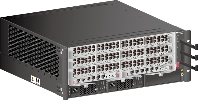
Figure 1 S9703 chassis (front view)

Figure 2 S9703 chassis (rear view)

Figure 2 S9703 chassis (rear view)

NOTE:

The S9703 chassis include FCC-certified chassis and common chassis.

Figure 3 shows the front structure of the S9703 chassis.
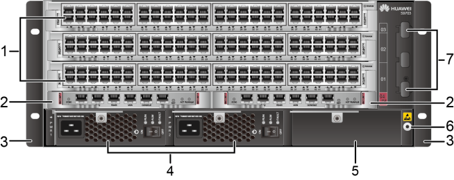
Figure 3 S9703 chassis structure (front view)
Figure 3 S9703 chassis structure (front view)
1. Three of the following service cards can be installed:

  • Value-Added Service Unit
  • Open Service Platform Unit
  • 100M Interface Card
  • 1000M Interface Card
  • GE/10GE Interface Card
  • 10GE Interface Card
  • 40GE Interface Card
  • 40GE/100GE Interface Card
  • 100GE Interface Card
NOTE:

The cards supported by a switch depend on the software version. For details, see Hardware Query Tool.

2. Two MPUs 3. A pair of mounting brackets

NOTE:

The mounting brackets are used to secure the chassis in the cabinet.

4. Two power modules 5. Reserved slot

NOTE:

Install a filler panel in the reserved slot.

6. Front ESD jack

NOTE:

The ground terminal of an ESD wrist strap can be inserted into this jack. The ESD wrist strap can provide ESD protection when the chassis is reliably grounded.

7. Cable management frames

NOTE:

Cable management frames are used to route cables.

Figure 4 shows the rear structure of the S9703 chassis.

Figure 4 S9703 chassis structure (rear view)
Figure 4 S9703 chassis structure (rear view)
1. One Fan Module 2. Rear ESD jack

NOTE:

The ground terminal of an ESD wrist strap can be inserted into this jack. The ESD wrist strap can provide ESD protection when the chassis is reliably grounded.

3. JG ground terminal

NOTE:

The JG ground terminal is used to ground the chassis.

4. Air filter

NOTE:

The air filter prevents dust from entering the chassis.

Slot Configuration on the Chassis

The S9703 chassis provides 3 LPU slots, 2 MCU slots, and 2 power supply slots.

Figure 5 shows the slot layout at the front of the S9703 chassis, and Figure 6 shows the slot layout at the rear of the S9703 chassis.
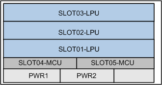
Figure 5 Slot layout on the S9703 chassis (front)
Figure 5 Slot layout on the S9703 chassis (front)
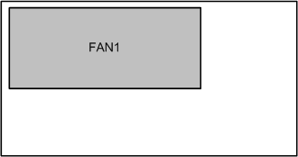
Figure 6 Slot layout on the S9703 chassis (rear)
Figure 6 Slot layout on the S9703 chassis (rear)

Table 2 describes the slot configuration in a chassis.

Table 2 S9703 slot configuration
Slot Type Slot ID Module Supported Remarks
MCU slot SLOT04 and SLOT05 MPUs The MCUs work in active/standby mode.
LPU slot SLOT01 to SLOT03
  • Value-Added Service Unit
  • Open Service Platform Unit
  • 100M Interface Card
  • 1000M Interface Card
  • GE/10GE Interface Card
  • 10GE Interface Card
  • 40GE Interface Card
  • 40GE/100GE Interface Card
  • 100GE Interface Card
NOTE:

The cards supported by a switch depend on the software version. For details, see Version Requirements for Components.

Power slot PWR1 and PWR2 power modules
Fan module slot FAN1 Fan Module

Power Supply Slot Configuration

 NOTE:

If a switch is running a version prior to V200R010C00, it does not allow combining the use of AC and DC power modules or power modules of different wattages. If the switch is running V200R010C00 or a later version, it allows combining the use of 2200 W AC and DC power modules. If the switch is running V200R012C00 or a later version, it allows combining the use of 2200 W AC, 2200 W DC, and 3000 W AC power modules.

The S9703 provides slots PWR1 and PWR2 for DC or AC power modules, as shown in Slot layout on the S9703 chassis (front).

The S9703 series switches support two redundancy modes of power modules: N+N, and N+0. The value of N depends on the maximum power actually required by the system. Ensure that the total maximum output power of N power modules (N x maximum output power of each power module) is larger than the maximum power actually required by the system. For example, the maximum power required by the system is 4000 W. If two 2200 W power modules are installed in the chassis, they work in 2+0 mode. The system can identify the power redundancy mode, and you do not need to manually configure the power redundancy mode. Table 3 describes the three power redundancy modes and the specific redundancy modes supported by the S9703 series switches.

Table 3 Description of power redundancy modes
Redundancy Mode Description Product Support
N+N
  • System power supply is not affected if no more than N power modules are removed or fail.
  • The maximum output power of the system is the total maximum output power of N power modules.
  • The first N represents mandatory power modules, and the second N represents optional power modules.
NOTE:

The N+N redundancy mode is often used when two power supply systems are available. In this case, the first N represents mandatory power modules for the first power supply system, and the second N represents mandatory power modules for the second power supply system. The use of double power supply systems provides redundancy for both power modules and power supply systems.

1+1 redundancy
N+0 (no redundancy)
  • System power supply is affected once any power module is removed or fails.
  • The maximum output power of the system is the total maximum output power of N power modules.
  • N power modules are mandatory, and there are no optional power modules.
1+0, and 2+0
 NOTE:

  • When using the N+N redundancy mode, equally divide the power modules into two groups and connect the two groups of power modules to two independent power supply systems. This configuration provides redundancy of power supply systems to enhance system reliability.
  • When using the N+N redundancy mode, you are advised to install N power modules (as specified by the first N) in the power supply slots at the left side and install N power modules (as specified by the second N) in the power supply slots at the right side. Power slots are marked PWR.
  • If the system power consumption exceeds 50% of a single power module’s power, all power modules equally share the power consumption. This reduces the load of a single power module and improves the system reliability.

The following describes the power module configuration for an S9703 switch with different power supplies:

  • If DC power input is provided, configure power modules according to DC power input.
  • If 220 V single-phase AC input or 110 V dual-live-wire AC input is provided, configure power modules according to AC power input (220 V single-phase or 110 V dual-live-wire input).
  • If 110 V single-live-wire AC input is provided, configure power modules according to AC power input (110 V single-live-wire input).

DC power input

Table 4 describes the power module configuration for the S9703 series switches when DC power input is provided.

Table 4 Power module configuration (DC power input)
Power Module Type Redundancy Mode Maximum Output Power
2200 W DC power module N+N A maximum of 2 (1+1) 2200 W DC power modules can be configured, providing a maximum output power of 2200 W.
N+0 (no redundancy) A maximum of 2 (2+0) 2200 W DC power modules can be configured, providing a maximum output power of 4400 W.

AC power input (220 V single-phase or 110 V dual-live-wire input)

 NOTE:

If the input voltage is 110 V, the dual-live-wire input mode is recommended. In this case, the maximum output power of a 3000 W AC power module is 3000 W, the maximum output power of a 2200 W AC power module is 2200 W, and the maximum output power of an 800 W AC power module is 800 W.

Table 5 describes the power module configuration for the S9703 series switches when 220 V single-phase or 110 V dual-live-wire AC power input is provided.

Table 5 Power module configuration (220 V single-phase or 110 V dual-live-wire AC power input)
Power Module Type Redundancy Mode Maximum Output Power
3000 W AC power module N+N A maximum of 2 (1+1) 3000 W AC power modules can be configured, providing a maximum output power of 3000 W.
N+0 (no redundancy) A maximum of 2 (2+0) 3000 W AC power modules can be configured, providing a maximum output power of 4400 W.
2200 W AC power module N+N A maximum of 2 (1+1) 2200 W AC power modules can be configured, providing a maximum output power of 2200 W.
N+0 (no redundancy) A maximum of 2 (2+0) 2200 W AC power modules can be configured, providing a maximum output power of 4400 W.
800 W AC power module N+N A maximum of 2 (1+1) 800 W AC power modules can be configured, providing a maximum output power of 800 W.
N+0 (no redundancy) A maximum of 2 (2+0) 800 W AC power modules can be configured, providing a maximum output power of 1600 W.

AC power input (110 V single-live-wire input)

 NOTE:

When 110 V single-live-wire AC power input is provided, the maximum output power of a 3000 W AC power module is 1500 W, the maximum output power of a 2200 W AC power module is 1100 W, and the maximum output power of an 800 W AC power module is 400 W. In this case, it is recommended that you use the N+1 or N+0 redundancy mode to increase the maximum output power of the system.

Table 6 describes the power module configuration for the S9703 series switches when 110 V single-live-wire AC power input is provided.

Table 6 Power module configuration (110 V single-live-wire AC power input is provided)
Power Module Type Redundancy Mode Maximum Output Power
3000 W AC power module N+N A maximum of 2 (1+1) 3000 W AC power modules can be configured, providing a maximum output power of 1500 W.
N+0 (no redundancy) A maximum of 2 (2+0) 3000 W AC power modules can be configured, providing a maximum output power of 3000 W.
2200 W AC power module N+N A maximum of 2 (1+1) 2200 W AC power modules can be configured, providing a maximum output power of 1100 W.
N+0 (no redundancy) A maximum of 2 (2+0) 2200 W AC power modules can be configured, providing a maximum output power of 2200 W.
800 W AC power module N+N A maximum of 2 (1+1) 800 W AC power modules can be configured, providing a maximum output power of 400 W.
N+0 (no redundancy) A maximum of 2 (2+0) 800 W AC power modules can be configured, providing a maximum output power of 800 W.

Heat Dissipation

 NOTE:

It is recommended that you replace the air filter of a device every six months.

The S9703 cooling system consists of fan modules and air filters. A fan module is located behind the air exhaust vent (rear of the chassis), and an air filter is located outside the air intake vent (left side of the chassis).

  • The S9703 has one fan module, located at the rear of the chassis. The fan module draws cold air into the chassis to dissipate heat generated by working components, ensuring that the chassis operates within a normal temperature range. For details about the performance and attributes of a fan module, see Fan Module.
  • The air filter prevents dust from entering the chassis with the airflow.

Airflow

 NOTE:

The S9703, S9706, and S9712 use the same airflow design.

The S9703 chassis uses a left-to-back airflow design. Cold air is drawn into the chassis from the left side, dissipates heat in the chassis, and is exhausted from the rear of the chassis. Figure 7shows the airflow in the chassis.

Figure 7 Airflow in the chassis
Figure 7 Airflow in the chassis

Air Filter

 NOTE:

The switches may use honeycomb air filters or non-honeycomb air filters. The switches with honeycomb air filters installed in all air filter slots comply with Federal Communications Commission (FCC) standards.

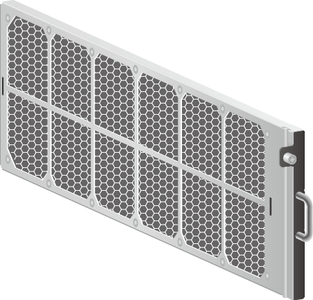
The S9703 uses either a sponge air filter or a honeycomb air filter. An FCC-certified chassis must use a honeycomb air filter. Figure 8 shows a sponge air filter, and Figure 9 shows a honeycomb air filter.
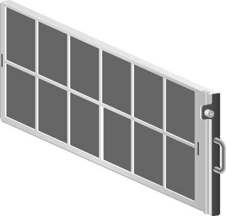
Figure 8 Sponge air filter
Figure 8 Sponge air filter
Figure 9 Honeycomb air filter
Figure 9 Honeycomb air filter

Specifications

Table 7 S9703 chassis specifications
Item Description
LPU slots 3
MCU slots 2
Fan slots 1
Power slots 2
Maximum port density

  • V200R001C00: 144xFE, 144xGE, 120x10GE
  • V200R002C00 and V200R003C00: 144xFE, 144xGE, 120x10GE, 24x40GE
  • V200R005C00 to V200R007C10: 144xFE, 144xGE, 144x10GE, 24x40GE
  • V200R008C00 to V200R009C00: 144xFE, 144xGE, 144x10GE, 24x40GE, 6x100GE
  • V200R010C00 and later versions: 144xFE, 144xGE, 144x10GE, 24x40GE, 12x100GE
Installation In an N66E or N68E cabinet
CSS Not supported
Maximum power consumption (fully loaded)

NOTE:

The heat dissipation value of a chassis equals the current power consumption of the chassis.
1185 W
Power specifications

  • DC input voltageRated voltage: -48 V DC/-60 V DC

    Maximum voltage range: -40 V DC to -72 V DC

  • AC input voltageRated voltage: 110 V AC/220 V AC, 50/60 Hz

    Maximum voltage range: 90 V AC to 290 V AC; 47 Hz to 63 Hz (The output power reduces to half of the maximum output when the input voltage is in the range of 90 V AC to 175 V AC.)

  • HVDC input voltage (3000 W AC)

    Rated voltage: 240 V DC

    Maximum voltage range: 190 V DC to 290 V DC

Dimensions (W x D x H, excluding rack-mounting brackets)

  • With cable management frames: 442 mm x 585 mm x 175 mm (17.4 in. x 23.0 in. x 6.89 in. (4 U))
  • Without cable management frames: 442 mm x 489 mm x 175 mm (17.4 in. x 19.3 in. x 6.89 in. (4 U))
Weight (empty/fully loaded) 11 kg/32.6 kg (24.3 lb/71.9 lb)
Reliability and availability
  • Mean time between failures (MTBF): 33.8 years
  • Mean time to repair (MTTR): 64 minutes
  • Availability: 0.9999964
NOTE:

The preceding values are calculated based on the typical configuration of the product. The actual values will vary depending on the modules installed on the product.

Environment specifications

  • Operating temperature and altitude:-60 m to +1800 m (197 ft. to 5906 ft.): 0°C to 45°C (32°F to 113°F)

    1800 m to 4000 m (5906 ft. to 13123 ft.): Operating temperature decreases by 1°C (1.8°F) every time the altitude increases 220 m (722 ft.).

    4000 m (13123 ft.): 0°C to 35°C (32°F to 95°F)

  • Operating relative humidity: 5% RH to 95% RH (noncondensing)
  • Storage temperature: -40°C to +70°C (-40°F to +158°F)
  • Storage altitude: < 5000 m (16404 ft.)
  • Storage relative humidity: 5% RH to 95% RH (noncondensing)
Noise at normal temperature (acoustic power)

≤ 72 dB(A)

Certification
  • EMC certification
  • Safety certification
  • Manufacturing certification
Part number
  • S9703 chassis: 02113547
  • S9703 chassis, FCC certified: 02113611

About Us

As a world leading Huawei networking products supplier, Hong Telecom Equipment Service LTD(HongTelecom) keeps regular stock of Huawei router and switch and all cards at very good price, also HongTelecom ship to worldwide with very fast delivery.

For related articles, visit the HongTelecom Blog and HongTelecom WordPress.
For real pictures of related product, visit the HongTelecom Gallery.
To buy related product, visit the HongTelecom Online Shop.

何诗名片

Huawei S9700 Series Switches Product

Product overview

The S9700 series terabit routing switches are high-end switches designed for next-generation campus networks and data centers to implement service aggregation.

Based on the Huawei Versatile Routing Platform (VRP), the S9700 provide high L2/L3 switching capabilities and integrate diversified services such as MPLS VPN, hardware IPv6, desktop cloud, video conferencing, and wireless access. In addition, the S9700 also provide a variety of reliability technologies including non-stop forwarding, hardware OAM/BFD, and ring network protection. These technologies improve customers’ network operation efficiency, maximize the device running time, and reduce customers’ Total Cost of Ownership (TCO).

An S9700 switch can be upgraded to an agile switch when it is equipped with X2S/X2E/X2H/X1E cards, the line cards with Huawei’s first Ethernet Network Processor (ENP). Agile switches allow customers to innovate their networks.

The S9700 series is available in three models: S9703, S9706, and S9712.

Product characteristics

Agile switch, enabling networks to be more agile for services

  • The S9700 series’ native AC capabilities allow enterprises to build a wireless network without additional AC hardware. Each S9700 switch can manage up to 2,048 APs and 32,768 users. It is a core switch that provides T-bit AC capabilities, avoiding the performance bottleneck on independent AC devices. The native T-bit AC capabilities help organizations better cope with challenges in the high-speed wireless era.
  • The S9700 series’ unified user management function authenticates both wired and wireless users, ensuring a consistent user experience no matter whether they are connected to the network through wired or wireless access devices. The unified user management function supports various authentication methods, including 802.1x, MAC address, and Portal authentication, and is capable of managing users based on user groups, domains, and time ranges. These functions control user and service management and enable the transformation from device-centered management to user-centered management.
  • Packet Conservation Algorithm for Internet (iPCA) changes the traditional method that uses simulated traffic for fault location. iPCA technology monitors network quality for any service flow at any network node, at any time, and without extra costs. It can detect temporary service interruptions within one second and can identify faulty ports accurately. This cutting-edge fault detection technology turns “extensive management” into “finely-granular management.”
  • Super Virtual Fabric 2.0 (SVF 2.0) technology can not only virtualize fixed-configuration switches into S9700 switch line cards but also can virtualize APs as switch ports. With this virtualization technology, a physical network with core/aggregation switches, access switches, and APs can be virtualized into a “super switch”, offering the simplest network management solution.
  • The S9700 series’ Service Chain function can virtualize value-added service capabilities, such as next-generation firewall. Then these capabilities can be used by campus network entities (such as switches, routers, ACs, APs, and terminals), regardless of their physical locations. Service Chain provides a more flexible value-added service deployment solution, which reduces equipment investment and maintenance costs.
  • The S9700 series supports IEEE 1588 v2 and Synchronous Ethernet (SyncE), meeting the high-precision synchronization requirements of network systems.

Innovative CSS technology

  • The S9700 switches support switch fabric clustering and service port clustering through Cluster Switching System (CSS) technology. CSS technology virtualizes multiple physical switches into one logical device that has higher reliability, switching efficiency, and flexibility and is easier to manage.
  • High reliability: Through hot-backup of routes, all control plane and data plane information is backed up and forwarded continuously at Layer 3, which significantly improves the reliability and performance of the device. Inter-chassis link aggregation can also be used to eliminate single-point failure and prevent service interruption.
  • Flexibility: Service ports can be used as cluster ports so that cluster members can be connected through optical fibers. This expands the clustering distance substantially.
  • Easy management: The member switches in a cluster are managed using the same IP address, which simplifies network device and topology management, improves operation efficiency, and reduces maintenance costs.

Carrier-class reliability

  • All the key components of the S9700s (including MPUs, power supply units, and fans) use a redundant design, and all modules are hot-swappable to ensure stable network operation.
  • The S9700s support hardware-based BFD for protocols such as static routing, RIP, OSPF, BGP, ISIS, VRRP, PIM, and MPLS. Hardware-based BFD greatly improves network reliability.
  • The S9700s support High-speed Self Recovery (HSR) technology. Using Huawei’s ENP cards, the S9700 implements end-to-end IP MPLS transmission network protection switchover within 50 ms, improving network reliability.
  • The S9700s support hardware-based Ethernet OAM, including comprehensive IEEE 802.3ah, 802.1ag, and ITU-Y.1731 implementations. Hardware-based Ethernet OAM can collect accurate network parameters, such as transmission latency and jitter, to help customers monitor network operating status in real time and to realize quick detection, location, and switching when a network fault occurs.
  • The S9700 supports graceful restart to realize non-stop forwarding and supports non-stop routing, ensuring reliable and high-speed operation of the entire network.

Powerful service processing capability

  • The S9700s’ multi-service routing and switching platform meets requirements for service transmission at the access layer, aggregation layer, and core layer of enterprise networks. The S9700 provides wireless access, voice, video, and data services, helping enterprises build an integrated full service network with high availability and low latency.
  • The S9700s support distributed Layer 2/Layer 3 MPLS VPN functions, MPLS, VPLS, HVPLS, and VLL. These functions allow enterprise users to connect to the enterprise network through VPNs.
  • The S9700s support many Layer 2/Layer 3 multicast protocols such as PIM SM, PIM DM, PIM SSM, MLD, and IGMP snooping, to support multi-terminal high-definition video surveillance and video conferencing services.
  • The software platform provides various routing protocols and supports large routing tables for both SME networks and large-scale multi-national company networks. Moreover, it supports IPv6, allowing an enterprise network to smoothly migrate to IPv6.

Powerful network traffic analysis

  • The S9700 switches support Netstream and V5/V8/V9 packet formats. The Netstream feature supports aggregation traffic template, real-time traffic collection, dynamic report generation and traffic attribute analysis, and traffic exception report. The S9700s send traffic statistics logs to master and backup servers to avoid data loss. The S9700s can realize real-time network monitoring and the traffic analysis of the entire network. They also provide applications and analysis including fault pre-detection, effective fault rectification, fast problem handling, and security monitoring, to help customers optimize network structure and adjust service deployment.

Comprehensive security measures

  • The S9700s support MAC security (MACSec) that enables hop-by-hop secure data transmission. Therefore, the S9700s can be applied to scenarios that pose high requirements on data confidentiality, such as government and finance sectors.
  • NGFW is a next-generation firewall card that can be installed on an S9700. In addition to the traditional defense functions such as firewall, identity authentication, and Anti-DDoS, the NGFW supports IPS, anti-spam, web security, and application control functions.
  • The S9700s provide comprehensive NAC solutions for enterprise networks. They support MAC address authentication, portal authentication, 802.1x authentication, and DHCP snooping-triggered authentication. These authentication methods ensure security of various access modes such as dumb terminal access, mobile access, and centralized IP address allocation.
  • The S9700s are the industry leader in integrated security solutions. It uses a 2-level CPU protection mechanism, and protects the CPU by separating the data plane and control plane. Additionally, the S9700s defend against DoS attacks and unauthorized access, and prevents control plane overloading.

Comprehensive IPv6 solution

  • The S9700s software and hardware platforms support IPv6 and the S9700s have been granted an IPv6 Network Access License and the IPv6 Ready Logo Phase 2 Certification from the Ministry of Industry and Information Technology.
  • The S9700 series supports various IPv6 unicast routing protocols (such as IPv6 static routing, RIPng, OSPFv3, IS-ISv6, and BGP4+) and multicast features (such as MLDv1/v2, MLD snooping, PIM-SM/DMv6, and PIM-SSMv6), which provides customers with comprehensive IPv4/IPv6 solutions.
  • The S9700 switches support various IPv4-to-IPv6 technologies: IPv6 manual tunnels, 6-to-4 tunnel, ISATAP tunnel, GRE tunnel, and IPv4-compatible automatic tunnels. These technologies ensure smooth transition from an IPv4 network to an IPv6 network.

Innovative energy conservation

  • The S9700s use a rotating ventilation channel to improve heat dissipation efficiency. In addition, they use a variable current chip to dynamically adjust the power according to traffic. Ports can go into a sleeping state when there is no traffic to reduce power consumption.
  • The S9700 series uses intelligent fan-speed adjustment technology. The fan module monitors and controls the temperature in each zone, and adjusts the fan speed of each zone individually. This technology extends the service life of each fan and reduces power consumption.
  • The S9700 switches support IEEE 802.3az Energy Efficient Ethernet, provide a low-power idle mode for the PHY line card, and switch to a lower power state during low link utilization.

Product specifications

Item S9703 S9706 S9712
Switching Capacity 2.88 Tbit/s; 5.76 Tbit/s 6.72 Tbit/s; 14.72 Tbit/s 8.64 Tbit/s; 18.56 Tbit/s
Packet Forwarding Rates 2,160 Mpps 2,880 Mpps/5,040 Mpps 3,840 Mpps/6,480 Mpps
Service Slots 3 6 12
Wireless Network Management Native AC
AP access control, AP region management, and AP profile management
Radio profile management, uniform static configuration, and centralized dynamic management
Basic WLAN services, QoS, security, and user management
User Management Unified user management
802.1x, MAC address, and Portal authentication
Traffic- and time-based accounting
User authorization based on user groups, domains, and time ranges
iPCA Quality Awareness Marking real service packets to obtain real-time count of dropped packets and packet loss ratio
Counting number of dropped packets and packet loss ratio on devices and L2/L3 networks
SVF Virtualization Virtualizing Access Switches (ASs) and APs into one logical device to simplify management and maintenance
Two layers of ASs allowed in an SVF system
Third-party devices allowed between SVF parent and clients
VLAN Access, trunk, and hybrid interfaces supported
Default VLAN
VLAN switching
QinQ and selective QinQ
MAC address-based VLAN assignment
MAC Address Automatic learning and aging of MAC addresses
Static, dynamic, and blackhole MAC address entries
Packet filtering based on source MAC addresses
MAC address limiting based on ports and VLANs
STP/ERPS STP (IEEE 802.1d), RSTP (IEEE 802.1w), and MSTP (IEEE 802.1s)
BPDU protection, root protection, and loop protection
BPDU tunnel
ERPS (G.8032)
IP Routing IPv4 routing protocols, such as RIP, OSPF, BGP, and IS-IS
IPv6 dynamic routing protocols, such as RIPng, OSPFv3, ISISv6, and BGP4+
Multicast IGMP v1/v2/v3, IGMP v1/v2/v3 snooping
PIM-SM, PIM-DM, PIM-SSM
MSDP, MBGP
Fast leave
Multicast traffic control
Multicast querier
Multicast protocol packet suppression
Multicast CAC
Multicast ACL
MPLS MPLS functions
MPLS OAM
MPLS TE
Supports MPLS VPN/VLL/VPLS
Reliability LACP and E-Trunk
VRRP and BFD for VRRP
BFD for BGP/IS-IS/OSPF/static route
NSR, NSF, and GR for BGP/IS-IS/OSPF/LDP
TE FRR and IP FRR
Ethernet OAM (IEEE 802.3ah and 802.1ag) (hardware-based)
HSR
ITU-Y.1731
DLDP
QoS Traffic classification based on Layer 2 headers, Layer 3 protocols, Layer 4 protocols, and 802.1p priority
Actions of ACL, CAR, re-mark, and schedule
Queue scheduling algorithms, such as SP, WRR, DRR, SP + WRR, and SP + DRR
Congestion avoidance mechanisms, such as WRED and tail drop
H-QoS
Traffic shaping
Network Synchronization Ethernet synchronization
1588v2
Configuration and Maintenance Console, Telnet, and SSH login
Network management protocols, such as SNMP v1/v2/v3
File uploading and downloading using FTP and TFTP
BootROM upgrade and remote upgrade
Hot patches
User operation logs
Security and Management 802.1x authentication and portal authentication
MACsec
NAC
RADIUS and HWTACACS authentication for login users
Command line authority control based on user levels, preventing unauthorized users from using commands
Defense against DoS attacks, TCP SYN Flood attacks, UDP Flood attacks, broadcast storms, and heavy traffic attacks
1K CPU queues
Ping and traceroute functions based on ICMP packets
Supports remote network monitoring
Value-added Services Firewall
NAT
NetStream
IPSec
Load balancing
Wireless AC
IPS
Interoperability Interoperable with VBST (compatible with PVST/PVST+/RPVST)
Interoperable with LNP (similar to DTP)
Interoperable with VCMP (similar to VTP)
Energy Saving Supports IEEE 802.3az: Energy Efficient Ethernet (EEE)
Dimensions (H x W x D) 175 mm x 442 mm x 489 mm, 4U 441.7 mm x 442 mm x 489 mm, 10U 663.95 mm x 442 mm x 489 mm, 15U
Chassis Weight (empty) 11 kg 29 kg 37 kg
Operating Voltage DC: –40V to –72V
AC: 90V to 290V
Equipment Power Supply Capability 2,200W 4,400W 6,600W

*: The S9700s support the NGFW and IPS cards. For more specification information, see the brochures of the cards.

Ordering information

S9700 basic configuration

LE2BN66ED000 N66E DC Assembly Rack (Eight 60A Outputs, maximum 2,200W per output, 600 mm x 600 mm x 2,200 mm)

LE0BN66EAC N66E AC Assembly Rack (Eight 10A Outputs, maximum 1,600W per output, 600 mm x 600 mm x 2,200 mm)

LE2BN66EA000 N66E AC Assembly Rack (Four 16A Outputs, maximum 2,500W per output, 600 mm x 600 mm x 2,200 mm)

EH1BS9703E00 S9703 assembly chassis

EH1BS9706E00 S9706 assembly chassis

EH1BS9712E00 S9712 assembly chassis

EH1M00FBX000 Wide Voltage 74 Fan Box

Monitoring Unit (Sustain FCC)

EH1D200CMU00 Centralized monitoring unit

MPU

EH1D2MCUAC00 S9703 MCUA-clock (Sustain FCC)

EH1D2SRUDC00 S9706/S9712 SRUD-clock

EH1D2SRUC000 S9706/S9712, Main Control Unit C, Option clock

Service Subcards

EH1D2VS08000 8-port 10G Cluster Switching System Service Unit (SFP+)

LE0D00CKMA00 Clock Pinch Board-1588Service Processing Unit (Sustain FCC)

ET1D2FW00S00 NGFW Module A, with HW General Security Platform Software

ET1D2FW00S01 NGFW Module B, with HW General Security Platform Software

ET1D2FW00S02 NGFW Module C, with HW General Security Platform Software

ET1D2IPS0S00 IPS Module A, with HW General Security Platform Software

ACU2 WLAN ACU2 Access Controller Unit (128 AP Control Resource Included)

Power Supply Unit

W2PSA0800 800W AC Power Module (black)

IN6W18L10A AC Power Distribution Unit (Eight 800W Outputs, including power cable)

PAC-2200WF 2,200W AC Power Module

IM1W24APD AC Power Distribution Unit (Four 2,200W Outputs, including power cable)

W2PSD2200 2,200W DC Power Module (black)

EH1M00PDBS01 DC Power Distribution Unit (Eight 2,200W Outputs, including power cable)

Software

ES0SMS279700 S9700 Basic SW, V200R007

ES0SMS289700 S9700 Basic SW, V200R008

EH1SMS299700 S9700 Basic SW, V200R009

EH1SMS2A9700 S9700 Basic SW, V200R010

EH1SMS2B9700 S9700 Basic SW, V200R011

EH1SMPLS0000 MPLS Function License

EH1SNQA00000 NQA Function License

EH1SIPV60000 IPv6 Function License

EH1SSVFF0000 SVF Function License (applicable only to the S9700 series)

EH1SFIB128K0 X-series LPU FIB Resource License-128K

EH1SFIB512K0 X-series LPU FIB Resource License-512K

EH1SWL512AP0 WLAN Access Controller AP Resource License-512AP (with the X-series LPU used)

EH1SWL128AP0 WLAN Access Controller AP Resource License-128AP (with the X-series LPU used)

EH1SWL64AP00 WLAN Access Controller AP Resource License-64AP (with the X-series LPU used)

EH1SWL16AP00 WLAN Access Controller AP Resource License-16AP (with the X-series LPU used)

L-ACU2-128AP ACU2 Wireless Access Controller AP Resource License (128 AP)

L-ACU2-256AP ACU2 Wireless Access Controller AP Resource License (256 AP)

L-ACU2-384AP ACU2 Wireless Access Controller AP Resource License (384 AP)

L-ACU2-512AP L-ACU2-512AP

Documentation

EH1IV2RAC0E0 S9700 Series Switches V200R010C00 Product Documentation

ES1IV2RBC0E0 S9700 Series Switches V200R011C10 Product Documentation

Interface Card of S9700 Series Switch

About Us

As a world leading Huawei networking products supplier, Hong Telecom Equipment Service LTD(HongTelecom) keeps regular stock of Huawei S5300/ S2300/ S9300/ S1700/ S2700/ S5700/S6720/ S7700/ S9700/ S12700 all cards at very good price, also Hong Telecom Equipment Service LTD ship to worldwide with very fast delivery.