Huawei S9700 comes in the following models: S9703, S9706, and S9712. In this article, HongTelecom will introduce the Huawei S9703 switches.
S9700 Introduction
The S9700 series core routing switches (S9700 for short) are high-end switches designed for service integration in next-generation campus networks and data centers. Based on Huawei Versatile Routing Platform (VRP), the S9700 switches provide high-performance L2/L3 switching and integrate a range of services, such as MPLS VPN, hardware IPv6, desktop cloud, video conferencing, and wireless access. They also provide a variety of reliability technologies including in-service software upgrade, non-stop forwarding, hardware OAM/BFD, and ring network protection. These improve the network efficiency and maximize the normal operation time, thereby reducing the total cost of ownership (TCO).
The S9700 comes in the following models: S9703, S9706, and S9712. These models support a maximum of 3, 6, and 12 line processing units (LPUs), respectively.
Version Mapping
| CHASSIS | VERSION |
|---|---|
| S9703 chassis | V200R001C00 and later versions |
| S9703 chassis, FCC certified | V200R001C00 and later versions |
Appearance and Structure
NOTE:
The S9703 chassis is 4 U high (1 U = 44.45 mm). When the chassis has no cable management frame installed, the dimensions are 442 mm x 489 mm x 175 mm (W x D x H). When the chassis has cable management frames installed, the dimensions are 442 mm x 585 mm x 175 mm (W x D x H). Figure 1 and Figure 2 show the S9703 chassis.
Figure 1 S9703 chassis (front view)
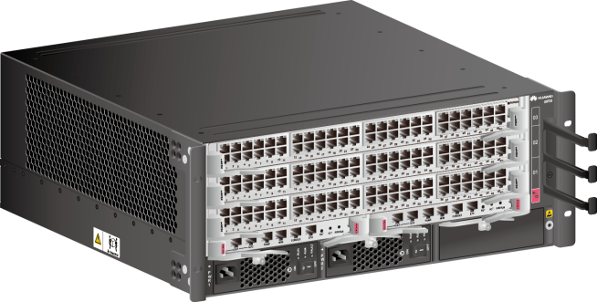
Figure 2 S9703 chassis (rear view)

The S9703 chassis include FCC-certified chassis and common chassis.
Figure 3 shows the front structure of the S9703 chassis.
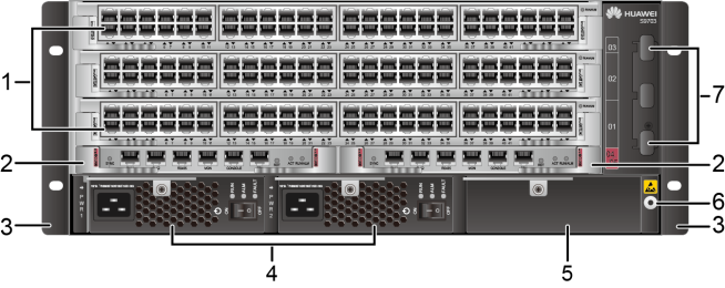
1. Three of the following service cards can be installed:
NOTE:
The cards supported by a switch depend on the software version. For details, see Hardware Query Tool. |
2. Two MPUs | 3. A pair of mounting brackets
NOTE:
The mounting brackets are used to secure the chassis in the cabinet. |
| 4. Two power modules | 5. Reserved slot
NOTE:
Install a filler panel in the reserved slot. |
6. Front ESD jack
NOTE:
The ground terminal of an ESD wrist strap can be inserted into this jack. The ESD wrist strap can provide ESD protection when the chassis is reliably grounded. |
| 7. Cable management frames
NOTE:
Cable management frames are used to route cables. |
– | – |
Figure 4 shows the rear structure of the S9703 chassis.
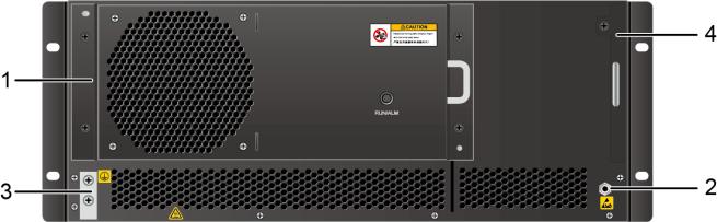
| 1. One Fan Module | 2. Rear ESD jack
NOTE:
The ground terminal of an ESD wrist strap can be inserted into this jack. The ESD wrist strap can provide ESD protection when the chassis is reliably grounded. |
3. JG ground terminal
NOTE:
The JG ground terminal is used to ground the chassis. |
| 4. Air filter
NOTE:
The air filter prevents dust from entering the chassis. |
– | – |
Slot Configuration on the Chassis
The S9703 chassis provides 3 LPU slots, 2 MCU slots, and 2 power supply slots.
Figure 5 shows the slot layout at the front of the S9703 chassis, and Figure 6 shows the slot layout at the rear of the S9703 chassis.
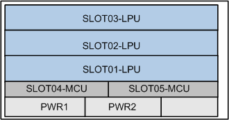
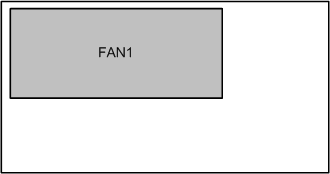
Table 2 describes the slot configuration in a chassis.
| Slot Type | Slot ID | Module Supported | Remarks |
|---|---|---|---|
| MCU slot | SLOT04 and SLOT05 | MPUs | The MCUs work in active/standby mode. |
| LPU slot | SLOT01 to SLOT03 |
|
NOTE:
The cards supported by a switch depend on the software version. For details, see Version Requirements for Components. |
| Power slot | PWR1 and PWR2 | power modules | – |
| Fan module slot | FAN1 | Fan Module | – |
Power Supply Slot Configuration
If a switch is running a version prior to V200R010C00, it does not allow combining the use of AC and DC power modules or power modules of different wattages. If the switch is running V200R010C00 or a later version, it allows combining the use of 2200 W AC and DC power modules. If the switch is running V200R012C00 or a later version, it allows combining the use of 2200 W AC, 2200 W DC, and 3000 W AC power modules.
The S9703 provides slots PWR1 and PWR2 for DC or AC power modules, as shown in Slot layout on the S9703 chassis (front).
The S9703 series switches support two redundancy modes of power modules: N+N, and N+0. The value of N depends on the maximum power actually required by the system. Ensure that the total maximum output power of N power modules (N x maximum output power of each power module) is larger than the maximum power actually required by the system. For example, the maximum power required by the system is 4000 W. If two 2200 W power modules are installed in the chassis, they work in 2+0 mode. The system can identify the power redundancy mode, and you do not need to manually configure the power redundancy mode. Table 3 describes the three power redundancy modes and the specific redundancy modes supported by the S9703 series switches.
- When using the N+N redundancy mode, equally divide the power modules into two groups and connect the two groups of power modules to two independent power supply systems. This configuration provides redundancy of power supply systems to enhance system reliability.
- When using the N+N redundancy mode, you are advised to install N power modules (as specified by the first N) in the power supply slots at the left side and install N power modules (as specified by the second N) in the power supply slots at the right side. Power slots are marked PWR.
- If the system power consumption exceeds 50% of a single power module’s power, all power modules equally share the power consumption. This reduces the load of a single power module and improves the system reliability.
The following describes the power module configuration for an S9703 switch with different power supplies:
- If DC power input is provided, configure power modules according to DC power input.
- If 220 V single-phase AC input or 110 V dual-live-wire AC input is provided, configure power modules according to AC power input (220 V single-phase or 110 V dual-live-wire input).
- If 110 V single-live-wire AC input is provided, configure power modules according to AC power input (110 V single-live-wire input).
Table 4 describes the power module configuration for the S9703 series switches when DC power input is provided.
| Power Module Type | Redundancy Mode | Maximum Output Power |
|---|---|---|
| 2200 W DC power module | N+N | A maximum of 2 (1+1) 2200 W DC power modules can be configured, providing a maximum output power of 2200 W. |
| N+0 (no redundancy) | A maximum of 2 (2+0) 2200 W DC power modules can be configured, providing a maximum output power of 4400 W. |
AC power input (220 V single-phase or 110 V dual-live-wire input)
If the input voltage is 110 V, the dual-live-wire input mode is recommended. In this case, the maximum output power of a 3000 W AC power module is 3000 W, the maximum output power of a 2200 W AC power module is 2200 W, and the maximum output power of an 800 W AC power module is 800 W.
Table 5 describes the power module configuration for the S9703 series switches when 220 V single-phase or 110 V dual-live-wire AC power input is provided.
| Power Module Type | Redundancy Mode | Maximum Output Power |
|---|---|---|
| 3000 W AC power module | N+N | A maximum of 2 (1+1) 3000 W AC power modules can be configured, providing a maximum output power of 3000 W. |
| N+0 (no redundancy) | A maximum of 2 (2+0) 3000 W AC power modules can be configured, providing a maximum output power of 4400 W. | |
| 2200 W AC power module | N+N | A maximum of 2 (1+1) 2200 W AC power modules can be configured, providing a maximum output power of 2200 W. |
| N+0 (no redundancy) | A maximum of 2 (2+0) 2200 W AC power modules can be configured, providing a maximum output power of 4400 W. | |
| 800 W AC power module | N+N | A maximum of 2 (1+1) 800 W AC power modules can be configured, providing a maximum output power of 800 W. |
| N+0 (no redundancy) | A maximum of 2 (2+0) 800 W AC power modules can be configured, providing a maximum output power of 1600 W. |
AC power input (110 V single-live-wire input)
When 110 V single-live-wire AC power input is provided, the maximum output power of a 3000 W AC power module is 1500 W, the maximum output power of a 2200 W AC power module is 1100 W, and the maximum output power of an 800 W AC power module is 400 W. In this case, it is recommended that you use the N+1 or N+0 redundancy mode to increase the maximum output power of the system.
Table 6 describes the power module configuration for the S9703 series switches when 110 V single-live-wire AC power input is provided.
| Power Module Type | Redundancy Mode | Maximum Output Power |
|---|---|---|
| 3000 W AC power module | N+N | A maximum of 2 (1+1) 3000 W AC power modules can be configured, providing a maximum output power of 1500 W. |
| N+0 (no redundancy) | A maximum of 2 (2+0) 3000 W AC power modules can be configured, providing a maximum output power of 3000 W. | |
| 2200 W AC power module | N+N | A maximum of 2 (1+1) 2200 W AC power modules can be configured, providing a maximum output power of 1100 W. |
| N+0 (no redundancy) | A maximum of 2 (2+0) 2200 W AC power modules can be configured, providing a maximum output power of 2200 W. | |
| 800 W AC power module | N+N | A maximum of 2 (1+1) 800 W AC power modules can be configured, providing a maximum output power of 400 W. |
| N+0 (no redundancy) | A maximum of 2 (2+0) 800 W AC power modules can be configured, providing a maximum output power of 800 W. |
Heat Dissipation
The S9703 cooling system consists of fan modules and air filters. A fan module is located behind the air exhaust vent (rear of the chassis), and an air filter is located outside the air intake vent (left side of the chassis).
- The S9703 has one fan module, located at the rear of the chassis. The fan module draws cold air into the chassis to dissipate heat generated by working components, ensuring that the chassis operates within a normal temperature range. For details about the performance and attributes of a fan module, see Fan Module.
- The air filter prevents dust from entering the chassis with the airflow.
Airflow
The S9703, S9706, and S9712 use the same airflow design.
The S9703 chassis uses a left-to-back airflow design. Cold air is drawn into the chassis from the left side, dissipates heat in the chassis, and is exhausted from the rear of the chassis. Figure 7shows the airflow in the chassis.

Air Filter
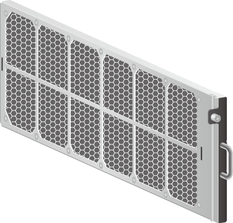
The switches may use honeycomb air filters or non-honeycomb air filters. The switches with honeycomb air filters installed in all air filter slots comply with Federal Communications Commission (FCC) standards.
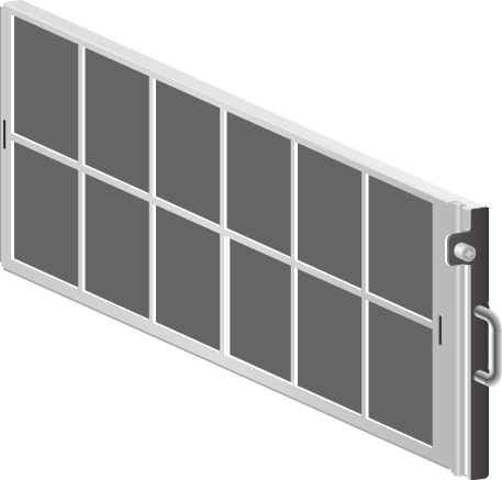
The S9703 uses either a sponge air filter or a honeycomb air filter. An FCC-certified chassis must use a honeycomb air filter. Figure 8 shows a sponge air filter, and Figure 9 shows a honeycomb air filter.
Specifications
About Us
As a world leading Huawei networking products supplier, Hong Telecom Equipment Service LTD(HongTelecom) keeps regular stock of Huawei router and switch and all cards at very good price, also HongTelecom ship to worldwide with very fast delivery.
For related articles, visit the HongTelecom Blog and HongTelecom WordPress.
For real pictures of related product, visit the HongTelecom Gallery.
To buy related product, visit the HongTelecom Online Shop.

